Partner POV | AI/ML Data Center Networking on Ethernet
In this article
This article was written by Ariel Cohen, Sr. Director of Architecture in the CTO Office, Michael Henkel, Distinguished Engineer in the CTO Office, and Raj Yavatkar, Cheif Technology Officer, at Juniper Networks.
This is the first in a series of technical blogs that will outline the key role that networking plays in AI/ML workloads – specifically, training and inference workloads. In this blog, we discuss the data transfer protocols and congestion considerations for such workloads. The series will cover a range of techniques, including fabric-based congestion control and load balancing, as well as endpoint-based (or endpoint-assisted) approaches.
Current State and Evolution of AI/ML Data Center Networking on Ethernet
In the realm of AI/ML workloads, handling large datasets is a critical challenge. Offloading the computation to GPUs significantly accelerates this task. However, the size of the data and often, the model (as with Large Language Models [LLMs]), typically exceeds a single GPU's memory capacity and multiple GPUs are commonly needed to achieve reasonable job completion times, particularly for training. To handle such workloads, different strategies are used based on specific AI/ML frameworks and use cases, requiring data and computation distribution across a cluster of GPU nodes.
As readers may already know, the cost of an AI data center is driven primarily by the number of GPUs used. In order to avoid idle GPU resources, a high-performance network interconnecting GPU nodes is required. Any slowdown in this networking layer can reduce the utilization of expensive GPUs, and negatively impact the job completion time.
Originating from the High Performance Computing (HPC) community, approaches utilizing Remote Direct Memory Access (RDMA) are now widely used in AI/ML cluster communication. RDMA facilitates data transfer by enabling zero-copy transfers between remote memory on multiple compute resources with GPUs (GPU nodes) over the network. This is done using a Reliable Connection (RC) transport protocol implemented in the network interface card (NIC) which imposes little to no load on the CPU or GPU. Originally designed for InfiniBand networks, RC has stringent requirements, including a lossless network and in-order packet delivery.
RDMA + Ethernet = ROCEv2
In the landscape of AI/ML training cluster networking, there is a growing interest in considering Ethernet-based networks as an alternative to InfiniBand. To enable RDMA in Ethernet networks, RDMA over Converged Ethernet version 2 (ROCEv2) has been developed, a protocol that encapsulates RDMA/RC protocol packets within UDP packets for transport over Ethernet networks.
Congestion in Clos-based Ethernet Fabrics
Ethernet fabrics, in their typical architecture for these applications, utilize a Clos topology, featuring leaf and spine layers. To provide a non-blocking network, the cumulative bandwidth of all leaf-to-node ports must match or be less than the combined bandwidth of all leaf-to-spine uplink ports. This setup ensures that nodes can use their full bandwidth without being slowed down by the connections between leaf and spine switches.
Within leaf-spine architectures, congestion can manifest in three primary areas:
- Between leaf and spine (TX queue of the leaf port toward the spine): Congestion arises during data transmission from leaf switches to spine switches. The TX queue of the leaf port may experience congestion, impacting communication between these switches.
- Between spine and leaf (TX queue of the spine port toward the leaf): Congestion manifests during the transmission of data from spine switches to leaf switches. The TX queue of the spine port may encounter congestion, impacting the intercommunication between these switches.
- Between leaf and node (TX queue of the leaf port toward the node): Congestion can occur in the data flow from leaf switches to individual nodes. The TX queue of the leaf port might suffer congestion, affecting the communication between leaf switches and connected nodes.
Leaf to Spine Congestion
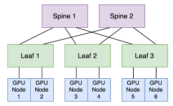
In this example, GPU nodes connected to one leaf switch have two potential routes to communicate with GPU nodes linked to another leaf switch. GPU nodes 1 and 2 can establish connections with GPU nodes 3 and 4 through either "leaf 1, spine 1 and leaf 2" or "leaf 1, spine 2 and leaf 2." The decision on the path to take is made by the leaf switch, employing an equal cost multipath (ECMP) load-balancing algorithm.
ECMP operates by generating a hash based on specific attributes (such as source/destination IP address, source/destination port and protocol) of incoming packets. Subsequent packets with matching hashes are directed to the same uplink towards the spine, forming what's known as a "flow" in ECMP. This flow-to-uplink mapping can be determined using various methods like Hash-Threshold mapping or Modulo-N mapping. ECMP aims to evenly distribute packets across available uplinks while preserving packet order within each flow. This method works efficiently for typical TCP-based applications where numerous short-lived sessions spread across multiple nodes create different hashes for each session, ensuring distribution across diverse uplinks.
However, challenges arise with long-lived flows. In scenarios where multiple high-bandwidth flows are hashed to share the same uplink, they can exceed the available bandwidth of that specific link, leading to congestion issues.
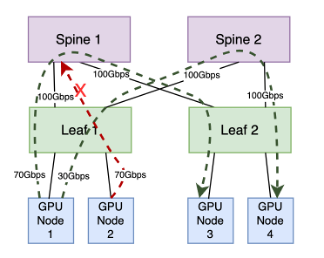
Examining the diagram above, the leaf-to-spine layer offers a combined bandwidth of 200Gbps across two paths. GPU node 1 generates two long-lived flows: one consuming 70Gbps via the first path and another consuming 30Gbps via the second path. GPU node 2 generates a long-lived flow utilizing 70Gbps. While the second path has adequate capacity for this flow, the ECMP algorithm might place it on the first path, which only has 30Gbps capacity remaining. This mismatch can overload the first path, causing congestion in the TX queue of the leaf ports and, ultimately, leading to dropped packets. The root cause of this suboptimal distribution lies in ECMP's simplicity; it lacks considerations for link utilization and quality in path selection, relying instead on a basic mechanism based on flow count.
Spine to Leaf Congestion
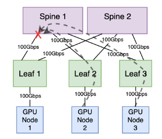
In this configuration, GPU node 2, linked to leaf 2, and GPU node 3, connected to leaf 3, are concurrently transmitting data at full bandwidth, each contributing 100Gbps traffic to GPU node 1 connected to leaf 1. Leaves 1, 2 and 3 redundantly connect to two spines, each equipped with a 100Gbps connection. The total available bandwidth between each leaf and the spine layer is 200Gpbs.
However, if both leaf 2 and leaf 3 utilize their uplinks to the same spine, the TX queue of the spine port toward the leaf switch connected to the receiving GPU node will experience congestion.
Leaf to Node Congestion
The second potential congestion point occurs in the communication between a leaf switch and a node, particularly when multiple senders transmit data to a single receiver, surpassing the receiver's bandwidth capacity. This is known as "incast" congestion.
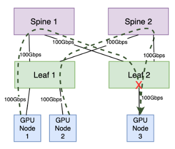
Assuming all node ports possess a bandwidth capacity of 100Gbps, GPU nodes 1 and 2 collectively transmit at full capacity, totaling 200Gbps. The leaf-to-spine layer can adequately handle the traffic destined for the leaf switch to which the receiver is connected. However, the leaf port to which GPU node 3 is attached has a bandwidth capacity of only 100Gbps. Consequently, half of the traffic destined for this port will be dropped due to the port's limited capacity (assuming no flow control or congestion management).
Impact on ROCEv2
- Traditional ECMP may result in suboptimal network utilization, congestion and pack drops between leaf and spine switches, especially with the long-lived high bandwidth ("elephant") flows prevalent in AI/ML workloads.
- Congestion at leaf to node ports can lead to packet drops when the combined sender bandwidth exceeds the receiver's capacity.
To achieve better network utilization, some enhanced load distribution techniques have appeared, such as Dynamic Load Balancing (DLB) providing "flowlet" based balancing or packet spraying which distributes traffic on a per packet basis. However, DLB might not be applicable to RDMA traffic and packet spraying can introduce out-of-order packet delivery. We will discuss further such techniques and their implications in a subsequent blog in this series.
In Ethernet fabrics, the challenges of lossy networks are typically managed at the protocol level (e.g., TCP), or the application level (e.g., VoIP with UDP). These protocols and applications are specifically designed to function efficiently in Ethernet environments.
However, RDMA using the RC protocol presents a challenge as it was originally designed for InfiniBand fabrics which provide lossless and in-order packet delivery. The RC protocol is highly sensitive to packet loss and out-of-order packet delivery. In RC, packets are sequenced, and if they are dropped or arrive out of order, the NIC might request re-transmission based on a "go-back-N" mechanism, which retransmits all packets from the last acknowledged packet. Connections may even need to be torn down and re-established as a result of timeouts caused by dropped packets. This significantly reduces communication performance, which results in reduced GPU utilization and longer job completion times in AI/ML clusters.
To tackle packet losses, out-of-order delivery and congestion problems in Ethernet for ROCEv2, alternative mechanisms must be employed.
How are the fabric requirements of RoCEv2 currently achieved?
The key requirement from the fabric is lossless packet delivery. This is achieved with a flow control technique called Priority-based Flow Control (PFC). The technique operates independently per priority (there are 8 priorities). This enables a receiver to pause the sender which is directly connected to it. When the receive buffer on the receiver fills to a threshold level, the receiver transmits a pause frame to the sender to temporarily stop the sender from transmitting more frames. The buffer threshold must be low enough so that the sender has time to stop transmitting frames and the receiver can accept the frames already on the wire before the buffer overflows. The pause frame includes a timeout which can be set to 0 (which effectively means resume sending). When the receive buffer empties to a level below another threshold, the receiver sends such a message to resume sending.
PFC can lead to undesirable network behavior, such as head of line blocking, congestion spreading and even deadlock. This motivates the use of Explicit Congestion Notification (ECN) in combination with PFC. With this technique, imminent congestion in the network is reported back to the traffic sources so that they reduce their injection rates. The injection rate is controlled per RoCE queue pair (QP) which is a NIC hardware resource corresponding to the communicating send and receive queues used by the application.
ECN is enabled on both endpoints (NICs) and all of the intermediate switches between the endpoints. Network devices mark the packets using the ECN field of the TOS field in the IP header. When an ECN-marked packet arrives at the destination NIC, a congestion notification packet (CNP) is sent to the source NIC and the source NIC reacts by reducing its injection rate on the QP specified in the CNP. An ECN threshold is set on switches. This is an egress threshold. Once an egress queue exceeds this threshold, the switch starts ECN marking the packets on that queue.
The combination of PFC and ECN for RoCEv2 is sometimes called Data Center Quantized Congestion Notification (DCQCN) or RoCEv2 Congestion Management (RCM). The correct operation of this technique requires setting PFC and ECN thresholds carefully to balance the following requirements:
- Ensuring that PFC is not triggered too early - that is, before giving ECN a chance to send congestion feedback to slow the flow.
- Ensuring that PFC is not triggered too late, thereby causing packet loss due to buffer overflow.
The DCQCN technique is the most prevalent approach and has been used successfully in RoCEv2 deployments. However, setting the PFC and ECN thresholds correctly can be challenging. Also, we noted that achieving the best network utilization requires balancing the load well on the network. These twin challenges motivate approaches that rely on enhancements at the endpoints (NICs) to facilitate improved solutions. Such approaches will be the main topic of a future blog in this series.