6 Steps to Understanding Cisco ACI
In this article
WWT has been working with Cisco Application Centric Infrastructure (ACI) since the first alpha and beta codes and taught thousands of customers on how to understand and deploy ACI. Through various discussions since its launch, we've helped organizations navigate the specifics and conclude whether ACI is right for the business.
Navigating ACI
We've come up with an easy guide to help organizations understand the technical aspects of ACI. The following six steps can help network engineers new to ACI understand the basic concepts.
Step 1
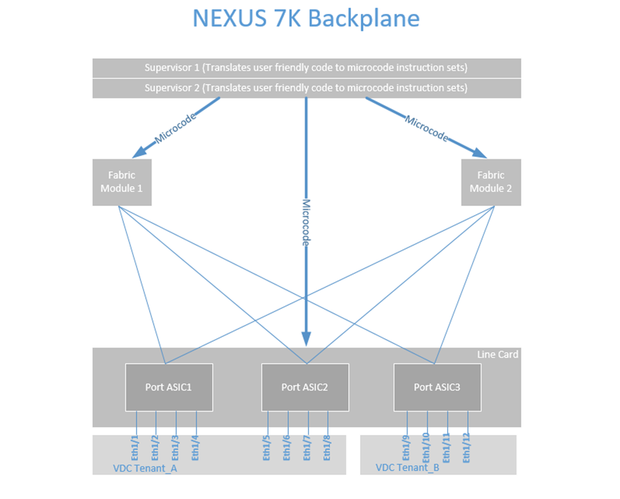
When discussing new architectures such as ACI, I draw parallels to familiar network infrastructures. 95 percent of the customers I interact with currently have (or have worked in the past with) the NEXUS 7K and Virtual Device Contexts (VDCs). This technology allows you to take the large Nexus 7K Physical Switch and carve out portions of CPU, Memory and Port ASICs from various line cards into smaller virtual or logical switches.
Understanding the similar concept of NEXUS VDCs helps with understanding ACI Tenants. In the example above, we have created two VDCs: Tenant_A and Tenant_B using a portion of memory and CPU from the parent switch. We also see that we have a 12 port NEXUS line card, and we have allocated ports 1/1-1/8 into VDC Tenant_A, and ports 1/9-1/12 into VDC Tenant_B.
We can use Role-Based Access (RBAC) to control who logs into these virtual switches; someone who is logging into Tenant_A sees port 1/1-1/8 and someone logging into Tenant_B sees ports 1/9-1/12. The full functionality of the NX-OS code is there to configure these ports as L2 or L3 ports and the NX-OS features of that code version.
The next step is how we interact to configure these virtual switches and ports. Like any standard network device, we log into the supervisor or device and apply user-friendly human-readable code to configure VLANs, Layer 3 routing, etc. The supervisor or device translates the user-friendly configuration into binary microcode and programs the various ASICs that allow the device to manipulate the packet forwarding.
This is how every stand-alone networking device works today. Technically there are ways to get into the ASICs and program with the actual microcode, but that's reserved for the OEM developers.
Step 2
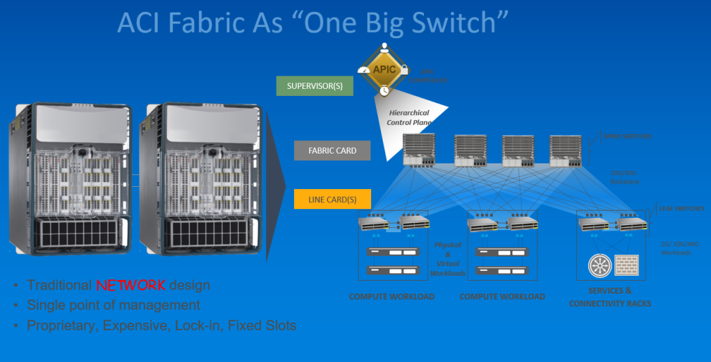
When ACI was created, the overall architecture was to create a "big switch" that could be logically carved up into small logical switches, just like a VDC. In ACI, the NEXUS 7K Supervisor role is replaced by the APICs, which is a Hierarchical Control Plane.
The NEXUS 7K fabric modules is replaced by the spine switches which connect to leaf switches. Finally, the ASICs in the NEXUS 7K line cards are replaced by leaf switches in ACI, and they can allocate to various Tenants (VDCs).
Step 3
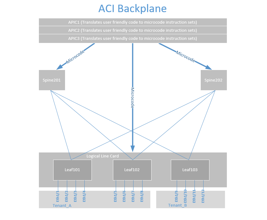
If we now look at what an ACI backplane would look like, we can see the similarity between a single NEXUS 7K switch with VDCs and an ACI "giant switch." Just as we discussed with the NEXUS and VDCs, we can take ports 1/1-1/4 out of Leaf 101, 1/5-1/8 out of Leaf 102 and allocate them to Tenant_A.
We can also allocate port 1/9-1/12 from Leaf 103 to Tenant_B. In a real-world design, you would want to map ports more consistently. This Tenant and the connectivity inside the Tenant can go across hundreds of switches in a data center and even across multiple data centers and even public cloud.
We also see that the APICs translate user-friendly human-readable code into microcode to program the spines and leafs just like we programmed the fabric modules and ASICs in a single NEXUS 7K. This is a critical juncture for the network engineer to understand because most feel we are giving up control of our infrastructure.
What we are actually doing is instead of configuring things box by box, we are creating one large switch, logging in to it and allowing the APICs to create the microcode to program this large switch, known as a fabric. There is no difference in this step compared to configuring a single NEXUS 7K. Allowing the NEXUS 7K to convert our NX-OS command-line configuration into microcode and apply it to a single switch and VDCs is no different than an APIC doing that same function to dozens or hundreds of spines, leafs and ACI Tenants.
Step 4

Now that we are comfortable with the APIC creating the microcode to program our "giant switch," let's look at how the ACI infrastructure self assembles. The first step is to bootstrap the APICs and configure each one via console and OOB.
The APICs will "discover" the leaf switches via LLDP that they are attached to, then those leaf switches are registered, given a DHCP address from the APIC and become part of the fabric. The leaf switches then discover the spines, the spines get DHCP addresses and become part of the fabric. The spines discover remaining leafs that are not attached to an APIC, and these get registered, get a DHCP address and become part of the "giant switch."
A good analogy would be inserting a line card to a NEXUS 7K and being prompted, "Do you want to add this line card Yes/No." Similar to the spines, it would be like adding a fabric module to the NEXUS 7K. All of this happens under the covers, just as is with NEXUS 7K line card or fabric module insertion.
Step 5
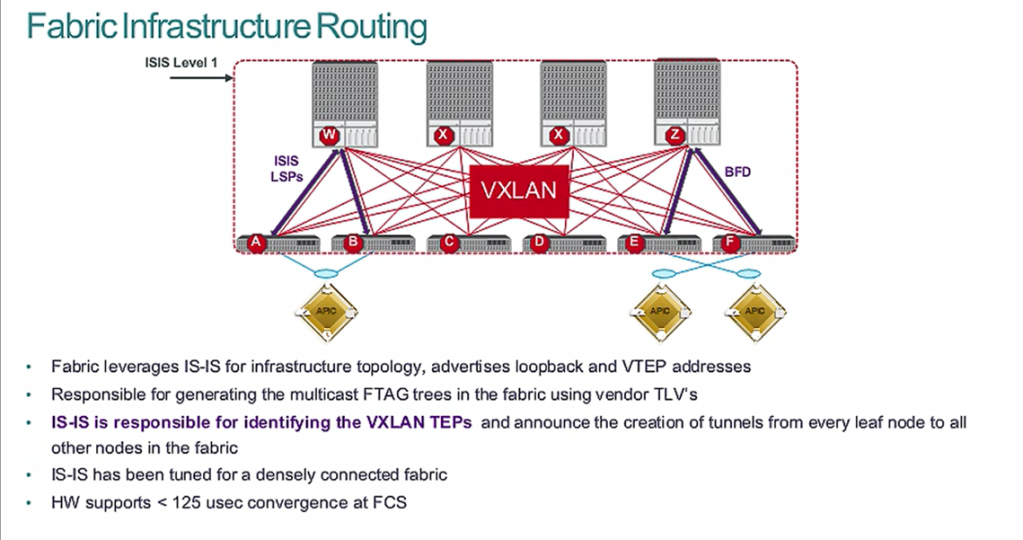
Once the fabric is discovered and registered, the fabric turns on IS-IS routing to create the Equal Cost Multi-Pathing (ECMP) routing for the DHCP addressing. This IS-IS routing is pre-configured and tuned for the fastest convergence.
This ECMP routing of the DHCP addresses (loopbacks) is what is called the underlay network. An overlay network is created using VXLAN encapsulation for connectivity between the ports and leaf switches. This VXLAN Tunnel Endpoint (VTEP) is bound to the loopback, and its reachability is via the underlay IS-IS ECMP routing table.
Just like we do not create the connectivity between the ASICs, fabric modules, backplane and supervisors in a NEXUS 7K, we allow ACI to do all this for us as well. What we do is create connectivity policies in the APIC to allow various leafs and ports to communicate via L2 and L3. The APIC will push the microcode just like a NEXUS 7K supervisor does.
Step 6
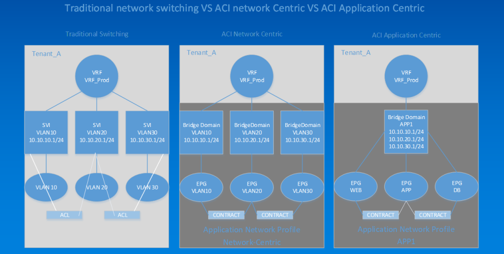
This final example shows us how to compare traditional switching with ACI "network-centric" and "application-centric" modes. In the left example, we see a VDC called Tenant_A, with a VRF called VRF_Prod. Connected to that are three SVIs for VLANs 10,20,30 and attached to that are VLANs 10,20,30. We then add ports from various line cards to the VLANs to get connectivity between devices. If we want to have filtering between the VLANs, we create ACLs and apply them to the SVIs, which is the way networking has been for decades.
In ACI we can have what is "network-centric" or "VLAN mapping" mode. We create the same constructs; instead of a VDC, we create a Tenant called Tenant_A and a VRF called VRF_Prod. What is different is the SVI is now called a bridge domain, and our VLANs are now called End Point Groups (EPGs). We also can apply filters between the EPGs using contracts (instead of ACLs). The significant difference is that a contract cannot be IP-to-IP specific but rather EPG-to-EPG specific.
We also have a mode known as "application-centric" mode. In this mode, we place all of our web workloads that require the same security filtering into a Web EPG and apply contracts to allow connectivity. One nice feature with this is that, quite often, a group of web servers may be across different subnets, and we can add all of our multiple subnets to our bridge domain (think IP Secondary on an SVI).
The challenge with application-centric mode is that you must know exactly what ports and protocols are traversing the network so you can create the proper filtering. The other challenge is Day 2, when an application owner upgrades or adds functionality and your filtering needs to be changed. Going application-centric requires a dedicated Application Dependency Mapping (ADM) tool.
Moving forward with ACI
When understood, these six steps will help anyone new to ACI to understand a more detailed technical discussion. To continue the ACI discussion, get started with a hands-on workshop.